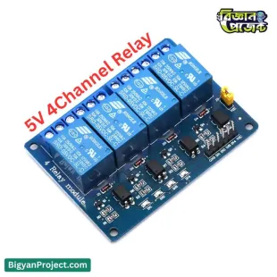
5V 6-Channel Optocoupler Relay Module for Arduino & MCU Control
Empower your low-voltage microcontroller projects to control high-power devices with the 5V 6-Channel Optocoupler Relay Module. This is an essential component for any hobbyist or student looking to move from digital signals to real-world control. Whether you're working with an Arduino, Raspberry Pi, or any other MCU, this board provides a safe and reliable bridge to switch AC lights, fans, motors, and other demanding loads. It's the perfect choice for your next DIY, robotics, or home automation project.
The key feature of this module is its onboard optocoupler isolation for each channel. This electrically isolates your sensitive 5V logic circuit (like an Arduino) from the high-voltage load, protecting your microcontroller from dangerous voltage spikes and electrical noise. This module is triggered by a Low-Level signal (Active LOW), meaning you simply send a GND signal from your MCU's digital pin to activate the relay. With 6 independent channels, you can manage multiple appliances from a single board, making it a powerful and efficient solution offered by Bigyan Project.
Product Specifications
| Feature |
Specification |
| Operating Voltage (VCC) |
DC 5V |
| Relay Power (JD-VCC) |
DC 5V |
| Number of Channels |
6 |
| Trigger Type |
Low-Level Trigger (Active LOW) |
| Isolation |
Optocoupler (Photocoupler) |
| Relay Type |
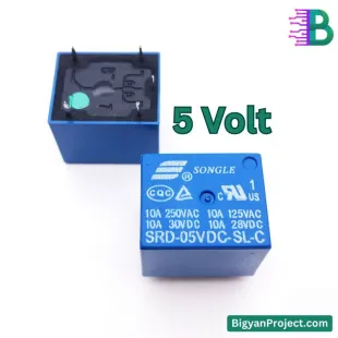
High-Quality SPDT Songle Relay |
| Max Load Rating (per channel) |
10A 250V AC or 10A 30V DC |
| Logic Signal Current |
~5-10mA (per channel) |
| Relay Coil Current |
~70mA (per channel, when active) |
| Status Indicators |
1 Power LED (Red), 6 Relay Status LEDs (Green) |
| Mounting |
4x 3.1mm fixed screw holes for easy installation |
| Relay Terminals |
COM (Common), NO (Normally Open), NC (Normally Closed) |
Features
- Multi-Channel Control: Features 6 independent relay channels to control multiple devices simultaneously.
- Robust Optocoupler Isolation: Protects your microcontroller from high-voltage surges and noise from the load side.
- High-Quality Songle Relays: Equipped with reliable SPDT relays, each providing Common, Normally Open, and Normally Closed terminals.
- Active LOW Trigger: Easily triggered by a 0V (GND) signal from your MCU, which is a common and simple logic to implement.
- Individual Status LEDs: Each channel has its own indicator LED that lights up when the relay is active, making debugging your project simple.
- Separate Power Supply: Features VCC and JD-VCC pins with a jumper, allowing you to power the relays and the logic side separately for complete isolation.
- Stable and Secure: Designed with 4 fixing screw holes (3.1mm diameter) for easy and secure mounting in your project enclosure.
Applications / Use Cases
- Home Automation: Control 220V AC lights, fans, and other home appliances directly from your Arduino or Raspberry Pi.
- Robotics Projects: Switch high-current DC motors, actuators, and linear actuators for complex robotic movements.
- DIY Electronics Projects: An essential component for any project from Bigyan Project that requires switching high loads.
- IoT (Internet of Things): Create smart devices that can be controlled over the internet, such as smart switches or automated garden sprinklers.
- Industrial Control: Suitable for basic PLC automation tasks and controlling small machinery.
- Science Fair Projects: Build impressive projects like automated systems, security alarms, or automated pet feeders.
User Guide / How to Use
Using this 6-channel relay module is straightforward. Here’s a basic guide:
- Powering the Module:
- VCC: Connect this to the 5V output pin of your microcontroller (e.g., Arduino 5V).
- GND: Connect this to the ground (GND) pin of your microcontroller.
- JD-VCC: This pin powers the relay coils. By default, it's connected to VCC with a jumper. For controlling small loads, you can leave the jumper on. For complete isolation, remove the jumper and provide a separate 5V power supply to the JD-VCC and its corresponding GND pin.
- Control Signals:
- IN1 to IN6: These are the trigger pins for each channel. Connect these to any 6 digital output pins on your microcontroller.
- Remember, this is a Low-Level Trigger module. To turn a relay ON, you must send a LOW signal (0V or `digitalWrite(pin, LOW);`). To turn it OFF, send a HIGH signal (5V or `digitalWrite(pin, HIGH);`).
- Connecting Your Load (e.g., an AC Light Bulb):
- COM (Common): This is the middle terminal. Connect your load's "hot" wire (e.g., the AC Live wire) to the COM terminal of one channel.
- NO (Normally Open): When the relay is OFF, this terminal is disconnected. When the relay is ON (triggered), it connects to COM. Connect the other wire from your light bulb to this terminal.
- NC (Normally Closed): When the relay is OFF, this terminal is connected to COM. When the relay is ON, it disconnects. This is used for loads you want to be on by default and turn off.
- The neutral wire of your AC load connects directly to the AC neutral source. Warning: Always be extremely careful when working with high-voltage AC electricity.
Frequently Asked Questions (FAQs)
- Q: What does "Optocoupler Isolation" mean?
A: It means there is an internal LED and a light sensor that separates your microcontroller circuit from the high-voltage relay circuit. This prevents any dangerous voltage from the load side from flowing back and destroying your Arduino.
- Q: What is a "Low-Level Trigger"?
A: It means the relay activates (closes the circuit) when you apply a LOW (0V / GND) signal to the IN pin. A HIGH (5V) signal will deactivate it.
- Q: What is the purpose of the VCC/JD-VCC jumper?
A: The jumper links the logic power (VCC) and the relay coil power (JD-VCC). For full isolation and to avoid overloading your MCU's voltage regulator, remove the jumper and provide a separate 5V, high-current power supply to JD-VCC and the adjacent GND pin.
- Q: Can I use this with a 3.3V microcontroller like a Raspberry Pi or ESP32?
A: Yes. Since it is a low-level trigger, a 3.3V logic 'LOW' (which is 0V) will correctly trigger the relay. A 3.3V 'HIGH' signal will also be correctly interpreted as 'HIGH' (release), making it compatible.
- Q: How much current does this module draw?
A: Each relay coil draws about 70mA when active. If all 6 relays are on, the relay coils alone (JD-VCC) will draw approximately 420mA (70mA * 6). Your 5V power supply must be able to handle this.
Challenges and Considerations
- Power Supply Requirement: With all 6 relays active, the module demands over 400mA. The onboard 5V regulator on an Arduino UNO cannot supply this much current. Always use a separate, external 5V power supply for JD-VCC.
- Inductive Loads: When switching inductive loads like motors or solenoids, a high-voltage spike (back-EMF) can occur when the relay turns off. This can damage the relay contacts over time. Consider adding a snubber circuit or flyback diode across the load terminals.
- AC Wiring Safety: Working with 250V AC is extremely dangerous. Always double-check your connections and ensure all high-voltage parts are properly insulated. Turn off all power before making changes.
- Trigger Logic: Remember that LOW = ON and HIGH = OFF. This can be counter-intuitive for beginners.
Compatibility
- All 5V microcontrollers like Arduino UNO, Nano, Mega, and Leonardo.
- 3.3V microcontrollers including Raspberry Pi (all models), ESP32, ESP8266, and NodeMCU.
- Other digital logic circuits or sensors that provide a digital LOW/GND output signal.
- PLC (Programmable Logic Controller) digital outputs.
Future Enhancement Options
- Combine this module with an ESP8266 or ESP32 to create a Wi-Fi-controlled smart switch for your home.
- Pair it with a Bluetooth module (like HC-05) to control your devices from a custom smartphone app.
- Integrate sensors (like temperature, light, or motion) to trigger the relays automatically for a fully automated system.
- Design and 3D print a custom enclosure to safely house the module and all high-voltage wiring.
Benefits
- Maximum Safety: Optocoupler isolation provides the best protection for your valuable microcontroller.
- High Power Switching: Control loads up to 10A, allowing you to manage most standard home appliances.
- Multi-Project Flexibility: With 6 channels, you can manage complex projects with multiple outputs from one single board.
- Clear Visual Feedback: Onboard LEDs instantly show you which relays are active, making testing and debugging fast.
Note: This list is not exhaustive.
- Reliable Operation: Built with high-quality components for stable and long-lasting performance in your projects.
- Great Value: Get this powerful 6-channel module from Bigyan Project to unlock the next level of your DIY creations.
Conclusion
The 5V 6-Channel Optocoupler Relay Module is a robust, safe, and highly versatile tool for any electronics enthusiast in Bangladesh. It bridges the gap between low-power digital logic and high-power real-world applications. Whether you are building a smart home system, a complex robot, or a simple automated light switch, this module provides the reliability and safety you need. Get yours from বিজ্ঞান প্রজেক্ট (Bigyan Project) today and bring your most powerful ideas to life.
Keywords for Search: 5V 6 Channel Relay Module, 6 Channel Optocoupler Relay, 5V Relay Board, Arduino Relay Module 6 Channel, Low Level Trigger Relay, Songle Relay 5V, Home Automation Relay Module, Relay Module for MCU, Bigyan Project Relay, 5V 6-Way Relay, High Current Relay Module, Relay Module 10A 250V, Optocoupler Isolated Relay, 6 Channel Relay Module Bangladesh, Arduino Relay BD, 5V 6 Channel Relay Price in BD
Important Information
The product details on this page are collected from multiple reliable sources to provide you with the best information. However, minor discrepancies may occur. We recommend thoroughly checking the product labels, instructions, and warnings before use.
Note: Images shown are for illustration purposes only and may slightly differ from the actual product.
What is the price of 5V 6 Channel Optocoupler Relay Module in Bangladesh (BD)?
The latest price of 5V 6 Channel Optocoupler Relay Module in Bangladesh is ৳620 Taka. You can buy the 5V 6 Channel Optocoupler Relay Module at best price from বিজ্ঞান প্রজেক্ট.
 Science Projects
 Sensor & Modules
 Basic Components
 Development Boards
 Robotic Parts
 Drone Parts
 Tools & Accessories
 Power Sources
 Kits & Combo
 IC & Microchip
 Cables & Connectors
 Audio Components
 Our Services